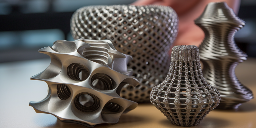
Precision engineering demands exactness, especially when it comes to assembling parts that must fit together tightly and securely. One common method used in manufacturing to achieve such reliable connections is known as a press fit.
Selecting the wrong tolerance can result in assembly failure, part deformation, or excessive wear over time. For machinists, engineers, and manufacturers alike, mastering press fit tolerance is not just a technical requirement; it’s a critical aspect of ensuring product performance and durability.
What is Press Fit?
A press fit, also known as an interference fit, refers to the assembly method where two mating components are joined together by friction after one part, typically a shaft or pin, is pressed into a hole or cavity that is slightly smaller in diameter.

To better understand how a press fit works, it helps to first clarify the two main parts involved in the fit:
- Shaft or Pin: This is the male component that is inserted into the mating part. It is typically made slightly larger than the hole it fits into, creating the necessary interference. Shafts or pins are often cylindrical and used in applications ranging from motor assemblies to gear mechanisms.
- Hole or Bore: This is the female component that receives the shaft or pin. It must be precisely machined to a slightly smaller diameter than the shaft to ensure a tight fit. Common examples include housings for bearings, bushings, or collars.
The resulting mechanical bond relies on the elastic deformation of materials and the frictional force generated between the contact surfaces. Unlike fasteners or adhesives, a press fit does not require additional joining elements, making it an efficient and reliable method for creating permanent or semi-permanent assemblies.
The success of a press fit hinges on achieving the correct interference—too tight and parts may crack during assembly; too loose and the connection may fail under load. That’s why understanding and applying the right press fit tolerance is fundamental in machining and precision manufacturing.
What Are the Different Types of Press Fits?
In mechanical engineering, press fits fall under the broader category of fit types that define how tightly two components, a shaft and a hole, fit together. The classification depends on whether there is space (clearance), overlap (interference), or a mix of both during assembly. Here’s a closer look at the three main types of fits relevant to press fit applications.

Clearance Fit
A clearance fit occurs when the shaft is always smaller than the hole, leaving space between the two components. This allows for easy assembly and disassembly without the need for force or special tools.
Clearance fits are typically used in parts that require regular maintenance or where free movement between components is needed, such as in sliding or rotating applications like guide pins or bearing housings. While not technically a press fit, it provides an important contrast when selecting tolerances.
Interference Fit
An interference fit, also known as a press fit or friction fit, is when the shaft is intentionally made slightly larger than the hole. The resulting interference generates pressure between the components, creating a firm and often permanent connection.
This type of fit is commonly used in applications that demand high structural integrity, such as mounting gears on shafts or seating bearings into housings. Interference fits require precise machining and may involve heat or mechanical force for assembly.
Transition Fit
A transition fit bridges the gap between clearance and interference fits. Depending on the exact tolerances of the shaft and hole, a transition fit may result in either a light press or a loose hold.
These fits offer a balance between ease of assembly and secure positioning, making them suitable for parts that may require occasional disassembly but must still maintain alignment, such as pulleys or collars.
Transition fits are often chosen when moderate holding strength is needed without the permanence of an interference fit. The three types of fits here are to provide readers with a quick visual summary.
|
Characteristic |
Clearance Fit |
Transition Fit |
Interference Fit |
|
Shaft vs. Hole Relationship |
Shaft is always smaller than the hole |
Shaft is slightly smaller or equal to the hole |
Shaft is larger than the hole |
|
Assembly Method |
Easy assembly by hand |
May require light force or tools |
Requires pressing or heating |
|
Holding Strength |
Low |
Medium |
High |
|
Typical Applications |
Guide pins, sliding parts, shafts requiring free movement |
Pulleys, collars, parts needing occasional disassembly |
Gears, bearings, structural joints requiring strong retention |
Tolerance in Press Fit
Tolerance in press fit refers to the allowable variation in dimensions between the mating parts – a shaft and a hole – that ensures a functional and secure fit. In manufacturing, no part can be made to an exact nominal dimension due to material inconsistencies and machining limits.
Tolerances define the permissible range of deviation for each component, ensuring that, even with slight variations, the assembled parts will perform as intended.
In a press fit, the goal is to achieve just the right amount of interference. If the shaft is too large or the hole too small beyond acceptable limits, assembly can become difficult or even damage the parts. On the other hand, if the interference is too little, the fit may not hold under operational stresses.
This is why defining and applying correct tolerances is so important. It balances ease of assembly with the strength and reliability of the joint, all while accounting for practical machining capabilities. The tighter the tolerance, the more precise the machining, and the higher the cost.
Press Fit Tolerance Chart
The chart below summarizes the critical dimensional parameters and recommended tolerances for designing and evaluating press fits, particularly for cylindrical pins.

To help you interpret the chart more effectively, here are concise definitions of the terms used:
- Nominal Size: The general dimension designation for the pin, used as a reference point for manufacturing and design.
- Nominal Pin Diameter: The basic (ideal) diameter of the pin before any tolerance or variation is applied.
- Pin Diameter, A: The actual diameter of the pin, which may vary slightly within a specified tolerance. This is divided into:
- Standard Series Pins: Typically used for general applications.
- Oversize Series Pins: Slightly larger pins designed for tighter press fits or worn-out holes.
- Point Diameter, B: The maximum and minimum diameters at the pointed end of the pin, which assist in alignment during assembly.
- Crown Height, C: The height of the domed top of the pin, important for insertion dynamics and stress distribution.
- Crown Radius, R: The radius of curvature of the pin’s crown, affecting how the load is transferred upon insertion.
- Range of Preferred Lengths, bL: The commonly recommended lengths for the pins, offering flexibility in various assembly designs.
- Single Shear Load: The estimated load the pin can resist in single shear when made from carbon or alloy steel, expressed in pounds (lbs). This helps determine the structural strength of the joint.
- Suggested Press Fithole Diameter: The recommended range (maximum and minimum) for the hole into which the pin is inserted, ensuring optimal press fit performance.
Key Factors Influencing Tolerance in Press Fit
In machining, determining the appropriate press fit tolerance isn’t just about picking values from a chart; it involves careful consideration of several technical and practical factors. These influence not only how the components will be assembled but also how the joint will perform over time. Below are the key factors that machinists and engineers must evaluate when defining press fit tolerances.
Materials
The hardness, elasticity, and thermal behavior of materials used for both the shaft and the hole play a major role in defining press fit tolerances. Softer materials like aluminum deform more easily under pressure, allowing for greater interference without cracking.
Harder materials, such as hardened steel, require more precise fits to avoid excessive stress or failure. Material selection directly influences how much interference is acceptable and how the joint behaves under load or thermal expansion.
Surface Finish
A smoother surface finish results in more predictable and consistent press fit behavior. Rough surfaces can increase friction unpredictably, making the fit tighter than expected or causing localized stress concentrations.
In machining, achieving the correct surface roughness ensures that tolerance values translate accurately into real-world performance. Precision grinding or polishing may be required in high-tolerance applications.
Thermal Expansion
When different materials are used for mating parts, each may expand or contract at a different rate with temperature changes. This is particularly important in environments with significant thermal variation. For example, a steel shaft in an aluminum hole may loosen or tighten depending on temperature. Machinists must account for these changes during the design phase to maintain reliable fits across operating conditions.
Manufacturing Tolerances
Even with the best design intentions, no machining process is perfect. Equipment wear, tool deflection, and environmental conditions all introduce variations. As such, achievable manufacturing tolerances should always be considered when specifying fits.
Overly tight tolerances can increase rejection rates and machining costs, while looser tolerances may compromise function. Balancing precision with practicality is key.
Assembly Method
Whether parts are assembled at room temperature, with heating (thermal expansion), or by mechanical pressing affects how much interference can be tolerated. Thermal methods allow for tighter fits without damage, while cold pressing requires more conservative tolerances to avoid part deformation. Understanding the assembly process helps in selecting the optimal fit strategy.
How to Calculate Tolerance Press Fit?
Calculating press fit tolerance involves more than just picking a tight clearance; it requires understanding the allowable dimensional limits that guarantee a secure fit without damaging the parts during assembly.
The right tolerance ensures optimal interference between the shaft and the hole, leading to a reliable mechanical connection that can withstand operational stresses such as shear forces, vibrations, and thermal expansion.
Interference Fit Range
At the core of the press fit tolerance calculation is the interference value, which is the difference between the hole’s diameter and the shaft’s diameter. In general:
Interference (I) = D(shaft) − D(hole)
Where:
- Dshaft = actual or maximum shaft diameter
- Dhole = actual or minimum hole diameter
To achieve a secure fit, the interference must be positive, meaning the shaft is slightly larger than the hole.
Tolerance Zone Considerations
Both the hole and the shaft have manufacturing tolerances. These are expressed as maximum and minimum limits:
Minimum Interference = Dshaft(min) − Dhole(max)
These equations define the interference range. The goal is to ensure that even with the worst-case tolerances, the fit remains within acceptable performance limits—neither too tight to assemble, nor too loose to maintain holding strength.
Example:
Let’s say you are fitting a 10 mm shaft into a hole.
- Shaft diameter tolerance: 10.03 mm (max), 10.01 mm (min)
- Hole diameter tolerance: 9.98 mm (min), 9.96 mm (max)
Then:
- Minimum interference = 10.01 – 9.96 = 0.05 mm
- Maximum interference = 10.03 – 9.98 = 0.05 mm
In this case, the interference is constant at 0.05 mm, meaning a very controlled and predictable fit.
Common Press Fit Interference Guidelines
As a rule of thumb, the recommended interference values depend on the diameter of the shaft and the application type:
|
Shaft Diameter Range |
Typical Interference (mm) |
|
1 – 10 mm |
0.01 – 0.05 |
|
10 – 50 mm |
0.02 – 0.08 |
|
50 – 100 mm |
0.05 – 0.15 |
|
> 100 mm |
0.10 – 0.30 |
These values may vary depending on material, surface finish, and whether the fit is assembled cold or with thermal expansion.
Software and Standards
For precise applications, many engineers use design software or consult international standards like ISO 286, ANSI B4.1, or DIN ISO 286 to define the fit classes (e.g., H7/p6, H7/n6) that correspond to specific tolerance values. These standards offer tested and reliable interference ranges for various fit types.
Read more: ISO 2768: Explaining CNC Machining Tolerance Standards
Best Practices for Press Fit Tolerance in Machining
Implementing proper tolerance press fit practices is essential for ensuring consistent quality, durability, and functionality in mechanical assemblies. In machining environments, it’s not just about achieving a snug fit—it’s about maintaining performance under stress, minimizing material distortion, and aligning with production capabilities.
Here are several real-world applications where press fit tolerances are critical:
- Electric Motor Assemblies: Rotor shafts are often press-fitted into the laminated core to ensure a precise and vibration-free rotation. Improper tolerances here could lead to imbalance and energy loss.
- Automotive Components: In wheel hubs, gears, and bearings, press fits are used to secure parts under dynamic loads. Accurate tolerances ensure parts don’t loosen under thermal and mechanical stress.
- Aerospace Fastening: Press fitting is used in joining lightweight materials, such as titanium and composites. Tolerances must be extremely tight to maintain structural integrity under extreme conditions.
- Printed Circuit Boards (PCBs): Press-fit connectors are inserted into plated through holes without soldering. Proper tolerance ensures reliable electrical contact while avoiding PCB damage.
- Medical Device Manufacturing: Precision-fitted surgical instruments and implants rely on micro-tolerances to function accurately and safely in critical environments.
Applying these best practices ensures the intended balance between reliability and manufacturability. As with any precision engineering task, continuous feedback from prototyping and testing is essential to refining press fit designs for optimal performance.
Conclusion
Understanding and applying the right press fit tolerance is essential for achieving reliable, high-performance mechanical assemblies. A well-executed press fit not only enhances product integrity but also extends the life of the assembly across various industrial applications.
Xmake provides CNC machining services with fast online quoting, enabling efficient custom part production from uploaded CAD files.
Frequently Asked Questions
Q1. What is the tolerance for a press fit?
The general press fit tolerance typically ranges from 0.01 mm to 0.05 mm (10–50 microns), depending on the shaft and hole sizes, material properties, and required retention force. For example, for steel parts with a 10 mm nominal diameter, a common interference might be around 0.02 mm to 0.03 mm. Precision engineering standards such as ISO or ANSI provide fit classes (e.g., ISO H7/p6) to guide appropriate tolerances.
Q2. What is the tolerance of a press fit PCB?
In PCB press-fit applications, such as inserting compliant pins into plated through-holes, the tolerance is typically tighter and must account for pin deformation and hole plating thickness. Standard guidelines (e.g., IPC-2221) recommend a hole diameter tolerance of +0.05 mm / -0.00 mm relative to the pin’s compliant section. Exact values depend on the type of press-fit pin and the PCB stack-up.
Q3. What is the press fit tolerance for nylon?
For nylon or other thermoplastics, press fit tolerances are generally looser than for metals due to material softness and thermal expansion. Typical interference may range from 0.002 to 0.01 mm per mm of diameter, depending on wall thickness and application. It’s also common to use snap fits or adjust for creep and relaxation in long-term assemblies.
Q4. What is the surface roughness for a press fit?
A smoother surface finish improves contact and reduces damage during assembly. For effective press fits, recommended surface roughness values are typically Ra 0.8 to 1.6 µm. Excessive roughness can increase friction and wear, while surfaces that are too smooth may reduce grip due to lack of micro-asperities.